Medium Voltage Equipment Testing Services – Medium Voltage Electrical Testing

MEDIUM VOLTAGE EQUIPMENT TESTING SERVICES

Medium voltage equipment testing services help verify equipment condition, identify hidden defects, support safe commissioning, improve reliability, and reduce the risk of costly failures in critical electrical power systems.


Medium Voltage Equipment Testing Services for Reliable Operation, Safe Energization, and Reduced Failure Risk

Medium voltage electrical systems often represent the backbone of industrial facilities, utilities, data centers, power generation plants, and critical infrastructure operations. Unlike low-voltage equipment, medium voltage assets typically serve large portions of a facility and carry significantly higher consequences when failures occur. A single cable fault, breaker malfunction, insulation failure, or relay problem can affect production, utility service, plant operations, or critical facility uptime.

Even new equipment can develop problems during transportation, storage, installation, or commissioning. Existing equipment faces additional risks associated with aging insulation systems, contamination, moisture intrusion, mechanical wear, thermal stress, and deferred maintenance. Many of these issues remain hidden until a fault occurs.

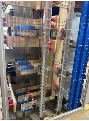
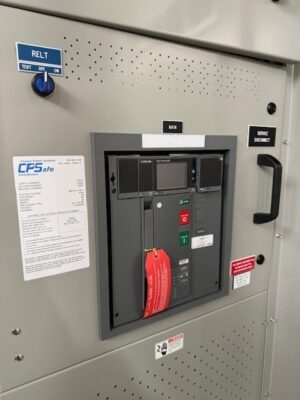
Coastal Power Systems provides medium voltage equipment testing services for switchgear, circuit breakers, protective relays, transformers, cables, motor control systems, substations, and associated power distribution equipment. These services help facility owners gain confidence that their equipment will operate safely and reliably when placed into service or returned to operation after maintenance activities.

Our Medium Voltage Equipment Testing Services

  • Medium voltage switchgear testing
  • Circuit breaker testing
  • Protective relay testing
  • Primary injection testing
  • Secondary injection testing
  • Transformer testing
  • Medium voltage cable testing
  • Insulation resistance testing
  • Commissioning and acceptance testing
  • NETA-guided testing

What Are Medium Voltage Equipment Testing Services?

Medium voltage equipment testing services involve the inspection, measurement, verification, and evaluation of electrical equipment operating above typical low-voltage distribution levels. These tests assess equipment condition, operational performance, protection system functionality, insulation integrity, and overall readiness for service.

Testing activities may be performed during equipment commissioning, preventive maintenance programs, modernization projects, outage work, troubleshooting efforts, or reliability improvement initiatives. Depending on the application, testing can include insulation testing, breaker performance testing, relay verification, cable diagnostics, transformer evaluations, grounding system assessments, and functional system testing.

The objective is to identify problems before equipment is subjected to actual operating conditions where failures become significantly more expensive and disruptive.

Why Medium Voltage Equipment Testing Matters

Many electrical failures begin as relatively small problems. Moisture enters a cable termination. A breaker mechanism becomes sluggish. Insulation gradually deteriorates. Relay settings are configured incorrectly. A transformer develops localized degradation. None of these issues may be obvious during routine operation.

Medium voltage equipment often operates under conditions where hidden defects can remain undetected for extended periods. When the equipment is finally exposed to a fault, switching operation, load increase, or abnormal condition, those hidden defects can quickly become major failures.

Medium voltage equipment testing helps uncover these conditions before they affect operations. Instead of relying on assumptions, facility owners gain objective information about equipment condition and performance, allowing corrective actions to be planned before reliability is compromised.

The Risks of Untested Medium Voltage Equipment

The consequences of medium voltage failures often extend far beyond the affected component. A cable failure can interrupt an entire production area. A breaker malfunction can expose equipment to damaging fault energy. A relay issue can result in unnecessary outages or delayed fault clearing. Transformer failures can require lengthy replacement schedules and significant capital expenditures.

Emergency repairs frequently require expedited parts procurement, overtime labor, and unplanned outages. The total cost of a major failure often exceeds the cost of comprehensive testing many times over.

Medium Voltage Testing During Commissioning

Commissioning is one of the most important phases of the equipment lifecycle. New medium voltage equipment may have been manufactured to specification, but field installation introduces additional variables that must be verified before energization. Shipping damage, wiring errors, improper assembly, contaminated components, and configuration mistakes can all occur between the factory and the jobsite.

Testing provides critical verification during this phase. Switchgear, breakers, relays, transformers, cables, and associated systems can be evaluated to confirm proper installation and operational readiness before the system enters service.

How Medium Voltage Equipment Testing Supports Reliability

Reliability programs depend on accurate information about equipment condition. Testing provides that information. Rather than relying solely on equipment age or visual inspections, engineers can evaluate actual performance characteristics and identify developing issues before failures occur.

Testing also provides valuable baseline information that supports predictive maintenance, future engineering studies, modernization planning, and long-term asset management.

Medium Voltage Cable Testing

Medium voltage cable systems represent a significant portion of electrical infrastructure risk. Insulation degradation, moisture intrusion, termination issues, installation damage, and aging effects often remain hidden until a fault occurs.

Depending on the application, cable testing may include insulation resistance testing, continuity testing, diagnostic evaluations, and acceptance testing. These activities help determine cable condition and identify problems before service interruptions occur.

Medium Voltage Breaker and Relay Testing

Protection systems are only as effective as the equipment responsible for detecting and clearing faults. Medium voltage breakers and relays must operate correctly during abnormal conditions to protect personnel, equipment, and facility operations.

Breaker testing evaluates mechanical performance, timing characteristics, contact condition, and operational functionality. Relay testing verifies protection settings, logic functions, communication systems, and coordination requirements. Together, these activities help ensure faults are detected and isolated correctly.

Electrical Testing and Asset Management

Testing provides valuable information for long-term asset management decisions. Equipment age alone rarely provides an accurate picture of reliability risk. Testing results help organizations prioritize maintenance activities, evaluate modernization opportunities, plan capital expenditures, and determine when equipment should be refurbished or replaced.

This data-driven approach often leads to better resource allocation, improved reliability, and lower lifecycle costs.

Industries That Benefit Most from Medium Voltage Equipment Testing

Medium voltage equipment testing services benefit utilities, power generation facilities, industrial manufacturing plants, petrochemical operations, refineries, mining operations, transportation systems, municipal infrastructure, water treatment facilities, and data centers. In each of these industries, reliable electrical infrastructure is essential for maintaining continuous operations.

Why Coastal Power Systems?

Medium voltage equipment testing is most effective when supported by broader electrical system expertise. Coastal Power Systems combines testing capabilities with engineering studies, NETA-guided testing, commissioning services, preventive maintenance programs, modernization projects, protective relay testing, and emergency response support.

This integrated approach allows testing results to be evaluated within the context of overall system reliability, operational requirements, equipment condition, and future planning objectives. Rather than simply identifying problems, Coastal helps facility owners develop practical strategies for improving long-term electrical system performance.

Request a Medium Voltage Equipment Testing Review

Whether you are commissioning new equipment, evaluating aging infrastructure, implementing a reliability program, or preparing for a modernization project, medium voltage equipment testing services can help improve confidence in your electrical system.

Contact Us


Frequently Asked Questions

What is medium voltage equipment testing?

Medium voltage equipment testing evaluates the condition, performance, and operational readiness of switchgear, breakers, relays, transformers, cables, and related electrical equipment.

Why is medium voltage testing important?

Testing helps identify hidden defects, improve reliability, support safe commissioning, and reduce the risk of costly equipment failures and outages.

When should medium voltage equipment be tested?

Testing is commonly performed during commissioning, preventive maintenance, modernization projects, equipment upgrades, and troubleshooting activities.

Can testing identify problems before equipment fails?

Yes. Many testing methods identify developing insulation, breaker, cable, or protection issues before they result in failures or outages.

Additional Information

The following organizations publish widely recognized standards, technical guidance, and best practices related to medium voltage equipment testing, electrical reliability, and power system maintenance.


Protective Relay Testing Services – Electrical Protection System Testing

PROTECTIVE RELAY TESTING SERVICES

Protective relay testing services help verify that electrical protection systems will operate correctly during fault conditions, reducing equipment damage, improving reliability, supporting worker safety, and minimizing the risk of costly outages.


Protective Relay Testing Services for Reliable Electrical System Protection and Fault Response

Protective relays are among the most important devices in an electrical power system. Under normal operating conditions, they monitor voltage, current, frequency, differential current, ground faults, and other electrical conditions. When an abnormal event occurs, the relay becomes the decision-maker. It determines whether a fault exists, identifies the affected portion of the system, and initiates breaker operation to isolate the problem before damage spreads throughout the electrical distribution network.

Protective relays cannot simply be installed and forgotten. Settings may be entered incorrectly during commissioning. System modifications can change coordination requirements. Relay firmware may be updated. Control wiring may be altered during maintenance activities. Equipment upgrades may introduce new fault current levels that affect protection performance. Even minor configuration errors can prevent a relay from operating correctly when needed most.

Coastal Power Systems provides protective relay testing services for utilities, industrial facilities, data centers, power generation plants, petrochemical operations, municipalities, and critical infrastructure where electrical reliability is essential to safe and continuous operation.

Our Protective Relay Testing Services

  • Protective relay functional testing
  • Relay setting verification
  • Secondary injection testing
  • Protection coordination verification
  • Differential relay testing
  • Generator protection testing
  • Transformer protection testing
  • Breaker failure scheme testing
  • Commissioning and startup testing
  • Relay troubleshooting and diagnostics

What Are Protective Relay Testing Services?

Protective relay testing services verify the performance, accuracy, settings, and operation of electrical protection devices throughout the power distribution system. These tests evaluate how relays respond to simulated fault conditions, abnormal operating scenarios, and protection system events. The goal is to confirm that relays detect faults correctly and initiate the appropriate protective actions within the required timeframes.

Testing typically involves specialized secondary injection equipment capable of simulating voltage and current conditions that the relay would experience during actual system faults. Engineers compare relay operation against design requirements, protection studies, manufacturer specifications, and system coordination objectives. The testing process also evaluates communication functions, logic schemes, interlocks, trip outputs, and associated protection system components.

Because modern relays perform many functions beyond simple overcurrent protection, comprehensive testing has become increasingly important as electrical systems become more sophisticated.

Why Protective Relay Testing Matters

Electrical protection systems are designed to minimize the impact of abnormal conditions. When a fault occurs, properly functioning relays should isolate only the affected portion of the system while allowing the remainder of the facility to continue operating. If a relay fails to trip, trips too slowly, or trips the wrong equipment, the consequences can be severe.

A delayed trip may expose equipment to damaging fault currents. An incorrect trip may shut down critical production processes unnecessarily. A failed protection system can allow a localized fault to escalate into a facility-wide outage. In extreme situations, improper relay operation can contribute to arc flash incidents, equipment destruction, and extended downtime.

Protective relay testing helps reduce these risks by confirming that protection systems will perform as intended before an actual fault occurs. For critical facilities, this verification often represents one of the most important reliability activities within the electrical maintenance program.

The Problem With Untested Protection Systems

Many facilities assume their protection systems are operating correctly simply because no obvious problems exist. However, relays may remain inactive for years without being required to respond to a significant fault. During that time, settings may be modified, firmware may change, system loads may increase, and equipment configurations may evolve.

Without testing, these changes can introduce hidden vulnerabilities. A relay setting entered incorrectly during commissioning may never be discovered until a fault occurs. A system expansion may alter fault current levels beyond the assumptions used during the original coordination study. A communication failure may prevent critical protection functions from operating properly.

The challenge is that these issues often remain invisible during normal operation. Relay testing provides a practical method for confirming that protection systems remain aligned with current operating conditions and engineering requirements.

How Protective Relay Testing Supports Reliability

Reliability depends on more than preventing failures. It also depends on limiting the consequences when failures occur. Protective relays serve as the first line of defense against electrical faults, equipment damage, and widespread outages. When protection systems operate correctly, fault events are isolated quickly and efficiently.

Protective relay testing helps maintain this capability by verifying that protection devices continue to perform according to design intent. Engineers can identify configuration issues, timing discrepancies, communication failures, and coordination concerns before they affect operations. This proactive approach reduces uncertainty and improves confidence in the electrical system.

For facilities where downtime carries significant operational or financial consequences, maintaining dependable protection systems is often just as important as maintaining the equipment they protect.

Protective Relay Testing and Power System Coordination

Protective relays do not operate independently. Each relay functions as part of a coordinated protection scheme designed to isolate faults selectively. Coordination studies determine which devices should operate first, how quickly they should respond, and how protection zones should interact throughout the electrical distribution system.

Relay testing helps verify that actual relay settings match the assumptions used during the coordination study. If settings have been altered, if equipment has been modified, or if system conditions have changed, the original coordination strategy may no longer function as intended. Testing provides an opportunity to identify these issues before they affect system performance.

This relationship between coordination studies and relay testing is one reason many organizations perform both activities together as part of a broader reliability and protection strategy.

When Should Protective Relays Be Tested?

Protective relay testing should be performed whenever new relays are installed, major modifications are made to the electrical system, protection settings are changed, or equipment undergoes commissioning. Testing is also recommended as part of ongoing maintenance programs because protection systems can change over time.

Many facilities establish periodic testing intervals based on equipment criticality, industry requirements, operating conditions, and reliability objectives. Critical facilities often test relays more frequently because the consequences of protection system failure are significantly greater.

Testing may also be warranted following major outages, fault events, equipment replacements, generator installations, utility service changes, or facility expansions that affect protection system operation.

Protective Relay Testing During Commissioning

Commissioning activities provide one of the most important opportunities for relay testing. New electrical systems often include dozens or even hundreds of protection functions that must operate correctly before energization. Verifying relay settings during commissioning helps ensure that the installed system matches the engineering design.

Testing during startup also confirms that field wiring, communication systems, trip circuits, breaker controls, and protection logic function correctly after installation. Identifying issues during commissioning is significantly less disruptive than discovering them after the facility enters service.

For EPC contractors, commissioning teams, and facility owners, relay testing helps reduce startup risk while supporting a smoother project turnover process.

Industries That Benefit Most from Protective Relay Testing Services

Protective relay testing services provide value wherever electrical reliability is critical. Utilities rely on protection systems to maintain grid stability and protect transmission and distribution infrastructure. Power generation facilities depend on relay performance to safeguard generators, transformers, and associated equipment. Data centers use sophisticated protection systems to support uptime objectives and maintain continuous operations.

Petrochemical plants, refineries, manufacturing facilities, mining operations, transportation systems, water treatment plants, and municipal infrastructure operators face similar challenges. In each of these environments, protection system performance directly affects reliability, safety, and operational continuity.

The greater the consequence of an outage, the greater the value of comprehensive relay testing.

Why Coastal Power Systems?

Protective relay testing services are most effective when performed within the broader context of electrical system performance. Coastal Power Systems combines relay testing capabilities with engineering studies, coordination studies, NETA-guided testing, commissioning services, preventative maintenance programs, modernization projects, and emergency response support.

This integrated approach allows relay testing results to be evaluated alongside protection coordination requirements, system reliability goals, equipment condition assessments, and future modernization plans. Rather than simply confirming that a relay operates, Coastal helps facility owners understand how protection system performance affects overall electrical reliability.

Because Coastal supports electrical infrastructure throughout its lifecycle, relay testing recommendations can be incorporated into broader reliability, maintenance, and asset management strategies.

Request a Protective Relay Testing Review

Whether you are commissioning a new facility, validating protection settings, troubleshooting relay performance, updating coordination studies, or improving electrical system reliability, protective relay testing services can help verify that your protection systems will perform when needed most.

Contact Us


Frequently Asked Questions

What are protective relay testing services?

Protective relay testing services verify that electrical protection devices operate correctly, respond to fault conditions as intended, and remain aligned with system protection requirements.

Why is protective relay testing important?

Testing helps ensure that protection systems will isolate faults correctly, minimize equipment damage, improve reliability, and reduce the risk of unnecessary outages.

How often should protective relays be tested?

Testing frequency depends on equipment criticality, industry requirements, operating conditions, maintenance strategies, and reliability objectives.

Can relay settings change over time?

Yes. Settings may be altered during maintenance activities, system modifications, firmware updates, equipment replacements, or operational changes, making periodic verification important.

What is the relationship between relay testing and coordination studies?

Coordination studies establish the intended protection strategy, while relay testing verifies that relay settings and operation match the assumptions used in the study.

Additional Information

The following organizations publish widely recognized standards, technical guidance, and best practices related to protective relay testing, protection system coordination, and electrical reliability.


Secondary Injection Testing Services – Protective Relay Testing & Verification

SECONDARY INJECTION TESTING SERVICES

Secondary injection testing services verify protective relay operation, confirm protection settings, validate control logic, and help ensure electrical protection systems respond correctly during abnormal operating conditions.


Secondary Injection Testing Services for Protective Relay Verification and Electrical System Reliability

Modern electrical power systems depend heavily on protective relays, electronic trip units, and intelligent protection devices to detect faults and isolate problems before equipment damage or widespread outages occur. These protection systems continuously monitor current, voltage, frequency, ground faults, differential conditions, and other electrical characteristics. When abnormal conditions are detected, protective devices must operate quickly and accurately to protect personnel, equipment, and facility operations.

Secondary injection testing services provide one of the most effective methods available for verifying protective relay performance without introducing high current into the primary electrical system. By injecting simulated electrical signals directly into relays, trip units, and protection devices, engineers can evaluate settings, timing characteristics, logic functions, communications, and operational performance under controlled conditions. This testing allows protection systems to be thoroughly validated before energization and throughout the equipment lifecycle.

Coastal Power Systems provides secondary injection testing services for utilities, industrial facilities, data centers, power generation plants, petrochemical operations, EPC contractors, and critical infrastructure projects. Whether supporting commissioning activities, relay upgrades, protection system maintenance, or troubleshooting efforts, secondary injection testing helps verify that protection systems will perform as intended when actual fault conditions occur.

Our Secondary Injection Testing Services

  • Protective relay testing
  • Relay setting verification
  • Trip unit testing
  • Protection scheme validation
  • Logic and interlock verification
  • Breaker trip circuit testing
  • Differential relay testing
  • Overcurrent protection testing
  • Generator protection testing
  • Commissioning and acceptance testing support

What Is Secondary Injection Testing?

Secondary injection testing is a method of verifying protective relay operation by injecting simulated electrical signals directly into the relay or protection device. Instead of introducing high current through the primary conductors, specialized test equipment generates voltage and current signals that replicate actual system conditions. These signals allow engineers and technicians to evaluate how the relay responds under various operating scenarios without energizing the power system.

Because the test signals are applied directly to the relay inputs, secondary injection testing is particularly effective for verifying relay settings, timing characteristics, logic functions, communication systems, and protection algorithms. Modern microprocessor-based relays contain sophisticated protection functions that can only be fully evaluated through comprehensive testing. Secondary injection testing provides a practical and efficient way to validate these functions before the relay is placed into service.

Why Secondary Injection Testing Matters

Protective relays perform a critical role within electrical power systems. Under normal operating conditions, they remain largely invisible to facility personnel. However, when a fault occurs, the relay must make rapid decisions that directly affect equipment protection, system stability, personnel safety, and operational continuity. A relay configured incorrectly may fail to operate when required, operate too slowly, or trip equipment unnecessarily.

Secondary injection testing helps eliminate uncertainty by verifying that relay settings and protection logic match the engineering design. Engineers gain confidence that overcurrent protection, differential protection, ground fault protection, undervoltage functions, frequency protection, and other protective elements will perform as intended. This verification becomes especially important in critical facilities where even a brief outage can have significant operational or financial consequences.

Secondary Injection Testing Versus Primary Injection Testing

Many facilities perform both secondary injection testing and primary injection testing because each method evaluates different aspects of the protection system. Secondary injection testing focuses primarily on the relay itself. Engineers inject simulated signals directly into the relay inputs and evaluate how the relay processes those signals. This approach is ideal for verifying settings, timing curves, logic functions, communications, and protection algorithms.

Primary injection testing evaluates the complete protection path by introducing actual current through the equipment. While primary testing verifies current transformers, sensors, trip units, relays, breaker mechanisms, and associated wiring as a complete system, secondary testing allows engineers to perform a deeper evaluation of the relay’s internal functions. The two methods complement each other and are often used together during commissioning and maintenance programs.

What Problems Can Secondary Injection Testing Identify?

Secondary injection testing frequently uncovers issues that are difficult to identify through visual inspection alone. Engineers often discover incorrect relay settings, configuration errors, communication failures, improper logic programming, timing discrepancies, protection element issues, and control circuit problems. Because modern relays are highly configurable, even minor programming errors can significantly affect system performance.

Protection settings may also drift away from the original engineering design over time. Equipment modifications, facility expansions, relay replacements, and maintenance activities can introduce changes that affect protection performance. Secondary injection testing helps identify these issues before they result in nuisance trips, protection failures, or equipment damage.

In facilities with complex protection schemes, testing often reveals coordination issues between multiple relays that might otherwise remain hidden until an actual fault event occurs.

How Secondary Injection Testing Supports Reliability

Electrical reliability depends heavily on the performance of protection systems. While equipment failures cannot always be prevented, the consequences of those failures can often be minimized when protection systems operate correctly. Secondary injection testing supports reliability by verifying that relays respond according to design intent and that protection settings remain aligned with current system conditions.

Facilities that routinely test protective relays generally experience fewer protection-related outages and are better positioned to identify developing issues before they affect operations. In addition, testing provides documentation that can support maintenance programs, reliability assessments, engineering studies, and future modernization projects. For organizations operating critical infrastructure, this information becomes an important part of long-term asset management strategies.

The Role of Secondary Injection Testing During Commissioning

Commissioning activities often involve complex protection systems that must be verified before energization. New switchgear installations, substation upgrades, generator projects, and modernization efforts frequently include multiple relays with sophisticated protection logic and communications requirements. Verifying these systems during commissioning helps ensure that the electrical infrastructure will perform correctly when placed into service.

Secondary injection testing allows engineers to validate relay operation under simulated fault conditions without exposing equipment to actual fault currents. Protection settings can be verified, trip outputs confirmed, control logic tested, and communication functions evaluated before the system is energized. This process significantly reduces startup risk and helps identify configuration issues that could otherwise delay project completion.

For EPC contractors and facility owners, successful commissioning often depends on the thorough verification of protection systems prior to turnover.

When Should Facilities Perform Secondary Injection Testing?

Secondary injection testing is commonly performed during acceptance testing, commissioning, relay upgrades, protection system modifications, maintenance programs, and troubleshooting activities. Facilities may also perform testing following major outages, system expansions, generator installations, or electrical modernization projects.

Periodic testing is particularly important for facilities operating critical electrical infrastructure. Because protection systems may remain inactive for long periods, routine verification helps ensure that relay settings remain correct and that protection functions continue to operate properly. Testing intervals vary depending on equipment criticality, operating conditions, maintenance strategies, and regulatory requirements.

Industries That Benefit Most from Secondary Injection Testing Services

Secondary injection testing services provide value wherever protective relays play a critical role in system operation. Utilities depend on relay performance to maintain service continuity and protect transmission and distribution infrastructure. Power generation facilities rely on sophisticated protection schemes to safeguard generators, transformers, and associated equipment. Data centers use relay protection to support uptime objectives and protect critical power distribution systems.

Industrial manufacturing facilities, petrochemical plants, refineries, mining operations, water treatment facilities, and transportation infrastructure operators also benefit from relay testing programs that help reduce operational risk. In all of these environments, protection system performance directly affects safety, reliability, and business continuity.

Why Coastal Power Systems?

Secondary injection testing services are most valuable when performed within the broader context of electrical system performance and reliability. Coastal Power Systems combines relay testing capabilities with engineering studies, NETA-guided testing, commissioning support, switchgear modernization, maintenance services, and lifecycle asset management programs. This integrated perspective allows testing results to be evaluated alongside system reliability objectives, protection coordination requirements, and future operational needs.

Because Coastal supports electrical infrastructure throughout its lifecycle, relay testing recommendations can be incorporated into engineering studies, modernization projects, maintenance strategies, and reliability improvement initiatives. The result is actionable information that helps facility owners maintain confidence in their protection systems while reducing operational risk.

Request a Secondary Injection Testing Review

Whether you are commissioning a new protection system, upgrading relays, troubleshooting nuisance trips, or implementing a preventive maintenance program, secondary injection testing services can help verify that your protection systems are configured correctly and operating as intended.

Contact Us


Frequently Asked Questions

What is secondary injection testing?

Secondary injection testing verifies protective relay operation by injecting simulated voltage and current signals directly into the relay, allowing engineers to evaluate settings, timing, logic functions, and protection performance.

Why is secondary injection testing important?

Secondary injection testing confirms that relays are configured correctly and will respond properly during fault conditions, helping improve safety, reliability, and equipment protection.

What is the difference between primary and secondary injection testing?

Secondary injection testing evaluates relay operation directly, while primary injection testing evaluates the complete protection system by introducing actual current through the equipment.

When should protective relays be tested?

Protective relays should be tested during commissioning, after setting changes, during maintenance programs, after major modifications, and periodically throughout their service life.

Can secondary injection testing identify relay programming errors?

Yes. Secondary injection testing is one of the most effective methods available for identifying incorrect relay settings, logic errors, timing issues, and configuration problems.

Additional Information

The following organizations publish widely recognized standards, technical guidance, and best practices related to protective relay testing, electrical equipment testing, and power system reliability.


Primary Injection Testing Services – Circuit Breaker & Protection System Testing

PRIMARY INJECTION TESTING SERVICES

Primary injection testing services verify that circuit breakers, protective devices, and electrical distribution systems operate correctly under real-world fault conditions, helping improve reliability, reduce operational risk, and support safe system operation.


Primary Injection Testing Services for Verifying Protection System Performance and Electrical Reliability

Electrical protection systems are designed to perform one of the most important functions within any power distribution network: detect abnormal conditions and isolate faults before equipment damage, safety incidents, or widespread outages occur. However, protection systems cannot be assumed to operate correctly simply because equipment appears functional. Circuit breakers, trip units, protective relays, current transformers, and associated control systems must work together under actual fault conditions.

Primary injection testing services provide one of the most comprehensive methods available for verifying protection system performance. Unlike many testing methods that evaluate individual components separately, primary injection testing evaluates the complete protection path by introducing actual test current through the equipment. This process confirms that current transformers, trip units, protective relays, breaker mechanisms, wiring systems, and associated components operate together as intended.

Coastal Power Systems provides primary injection testing services for utilities, industrial facilities, power generation plants, data centers, petrochemical operations, EPC projects, and critical infrastructure applications. Whether supporting new equipment commissioning, NETA-guided acceptance testing, preventive maintenance programs, or protection system troubleshooting, primary injection testing helps verify that critical electrical protection systems will respond properly when needed most.

Our Primary Injection Testing Services 

  • Circuit breaker primary injection testing
  • Protective relay verification
  • Trip unit performance testing
  • Current transformer verification
  • Overcurrent protection testing
  • Ground fault protection testing
  • Breaker trip function verification
  • Acceptance testing and commissioning support
  • Maintenance testing programs
  • Protection system troubleshooting

What Is Primary Injection Testing?

Primary injection testing is a method of verifying protective device operation by introducing high test current directly through the primary current path of the equipment. Because the current flows through the same conductors, current transformers, sensors, trip units, relays, and breakers used during actual operation, the test evaluates the complete protection system rather than isolated components. This approach provides a realistic assessment of how the equipment will perform during actual fault conditions.

The test current is generated using specialized primary injection test equipment capable of producing controlled high-current outputs. Engineers and technicians measure breaker trip times, verify relay operation, confirm current transformer performance, and evaluate protection system response under conditions that closely simulate real-world operation. Because the entire protection chain is evaluated, primary injection testing is often considered one of the most effective methods for validating electrical protection system performance.

Why Primary Injection Testing Matters

Many facilities rely heavily on protective devices to prevent catastrophic electrical failures. Circuit breakers, relays, and trip units operate silently in the background for years, often without being called upon to respond to significant fault events. The problem is that protection systems may appear healthy until the moment they are required to operate. A breaker that fails to trip, a relay configured incorrectly, or a current transformer wiring issue may remain hidden until a fault occurs.

Primary injection testing helps eliminate uncertainty by verifying actual system performance. Instead of assuming the protection system will operate correctly, facility owners gain measurable evidence that the equipment responds according to design requirements. This verification becomes especially important in facilities where a protection system failure could affect personnel safety, production operations, utility service continuity, or critical infrastructure reliability.

Primary Injection Testing Versus Secondary Injection Testing

One of the most common questions engineers ask is whether primary injection testing is necessary if secondary injection testing has already been performed. While both testing methods provide value, they serve different purposes and should not be viewed as interchangeable. Secondary injection testing evaluates protective relays and trip units by injecting signals directly into the relay or trip circuit. This approach verifies relay settings, logic functions, timing characteristics, and communication functions.

Primary injection testing goes further by evaluating the entire protection path. Because current is introduced through the primary conductors, the test verifies current transformers, wiring, sensors, trip units, relays, breaker mechanisms, and associated control circuits simultaneously. As a result, primary injection testing can identify problems that secondary testing alone may not detect. Many facilities use both methods because they provide complementary information about overall system performance.

What Problems Can Primary Injection Testing Identify?

Primary injection testing frequently identifies issues that would otherwise remain hidden until an actual fault event occurs. Common findings include improperly configured trip units, incorrect relay settings, current transformer wiring errors, breaker mechanical deficiencies, defective sensors, damaged wiring, and protection system calibration issues. In many cases, these conditions do not affect normal operation and therefore remain undetected during routine inspections.

The consequences of these issues can be significant. A breaker that trips too slowly may expose equipment to excessive fault energy. A relay configured incorrectly may fail to isolate a fault or may trip unnecessarily during normal operating conditions. Current transformer wiring errors can cause protection systems to receive inaccurate information, leading to unpredictable performance. Primary injection testing helps identify these risks before they affect operations.

How Primary Injection Testing Supports Reliability

Reliability depends on more than equipment condition alone. It also depends on the ability of protection systems to respond correctly during abnormal conditions. Many electrical failures become major outages not because the original fault was severe, but because the protection system failed to isolate the fault properly. When protective devices operate incorrectly, the impact of an event can expand far beyond the affected equipment.

Primary injection testing helps reduce this risk by verifying protection system performance under realistic operating conditions. Facilities gain confidence that breakers will trip when required, relays will respond correctly, and protection settings will function as intended. This confidence becomes particularly important in data centers, power generation facilities, utilities, petrochemical plants, and industrial operations where electrical reliability directly affects business performance.

The Role of Primary Injection Testing During Commissioning

Primary injection testing plays an important role during equipment commissioning and startup activities. Newly installed switchgear, switchboards, motor control centers, and distribution systems often include complex protection schemes that must be validated before energization. While factory testing verifies equipment before shipment, field installation introduces additional variables that can affect performance.

During commissioning, primary injection testing provides verification that field wiring, current transformers, breaker trip systems, protective relays, and associated controls function correctly after installation. This testing helps identify installation-related issues before the equipment enters service. For EPC contractors and facility owners, the result is a smoother startup process and a lower likelihood of protection system problems during initial operation.

When Should Facilities Perform Primary Injection Testing?

Primary injection testing is commonly performed during acceptance testing, commissioning, major maintenance activities, breaker upgrades, relay replacements, and protection system modifications. Facilities may also perform testing after significant outages, modernization projects, or major electrical system changes that affect protection schemes.

Many organizations incorporate primary injection testing into periodic maintenance programs for critical equipment. Because protection systems can drift over time due to aging, environmental conditions, or equipment modifications, periodic verification helps ensure continued performance throughout the equipment lifecycle. The appropriate testing interval depends on equipment criticality, operating conditions, maintenance history, and reliability objectives.

Industries That Benefit Most from Primary Injection Testing Services

Primary injection testing services provide value wherever electrical reliability is important. Utilities depend on protection system performance to maintain service continuity and protect electrical infrastructure. Power generation facilities rely on accurate protection operation to safeguard generators, transformers, and critical assets. Data centers require dependable protection systems to support uptime objectives and minimize operational disruptions.

Petrochemical facilities, refineries, manufacturing plants, water treatment facilities, and transportation infrastructure operators all benefit from verifying protection system performance before problems occur. Although the applications vary, the objective remains consistent: ensure that electrical protection systems operate exactly as intended when abnormal conditions arise.

Why Coastal Power Systems?

Primary injection testing services are most effective when performed within the broader context of electrical system reliability. Coastal Power Systems combines testing and commissioning services with engineering studies, relay testing, switchgear manufacturing, modernization projects, maintenance programs, and lifecycle support. This integrated approach allows testing results to be evaluated alongside overall system performance, reliability objectives, and future operational requirements.

Because Coastal supports facilities throughout the electrical asset lifecycle, primary injection testing recommendations can be incorporated into reliability initiatives, protection system improvements, modernization projects, and maintenance strategies. The result is actionable information that helps organizations improve safety, reduce operational risk, and maintain confidence in critical electrical infrastructure.

Request a Primary Injection Testing Review

Whether you are commissioning new switchgear, validating protection system upgrades, troubleshooting relay performance, or implementing a preventive maintenance program, primary injection testing services can help verify that your protection systems will perform when needed most.

Contact Us


Frequently Asked Questions

What is primary injection testing?

Primary injection testing verifies protective device operation by introducing actual test current through the primary current path of electrical equipment, allowing the complete protection system to be evaluated under realistic conditions.

Why is primary injection testing important?

Primary injection testing verifies that circuit breakers, relays, trip units, current transformers, and associated protection components operate together correctly during fault conditions.

What is the difference between primary and secondary injection testing?

Secondary injection testing evaluates relays and trip units directly, while primary injection testing evaluates the entire protection path by introducing current through the actual equipment conductors and current transformers.

When should primary injection testing be performed?

Primary injection testing is commonly performed during commissioning, acceptance testing, major maintenance activities, protection system upgrades, and periodic reliability programs.

Can primary injection testing improve reliability?

Yes. By verifying protection system performance before a fault occurs, primary injection testing helps reduce the risk of equipment damage, unnecessary outages, and protection system failures.

Additional Information

The following organizations publish widely recognized standards, technical guidance, and best practices related to electrical equipment testing, protection system verification, and electrical safety.


NETA-Guided Testing Services – Electrical Acceptance Testing & Commissioning

NETA-GUIDED TESTING SERVICES

NETA-guided testing services help verify equipment performance, reduce startup risk, identify installation deficiencies, and improve long-term reliability before electrical systems are placed into service.


NETA-Guided Testing Services for Reliable Startup, Commissioning, and Long-Term Electrical System Performance

Electrical equipment failures are often blamed on manufacturing defects, aging infrastructure, or unexpected operating conditions. In reality, many failures can be traced to problems that existed before the equipment was ever energized. Improper installation, shipping damage, loose terminations, incorrect relay settings, contaminated insulation systems, wiring errors, and assembly issues can all remain hidden until the electrical system is placed into operation.

Coastal Power Systems provides NETA-guided testing services for electrical equipment as part of a broader lifecycle approach that includes engineering studies, commissioning, maintenance, modernization, and emergency response support. Rather than treating testing as a standalone activity, Coastal views testing as a critical step in establishing the reliability foundation upon which the electrical system will operate for decades.

Our NETA-Guided Testing Services 

  • NETA-guided acceptance testing
  • Electrical equipment commissioning support
  • Switchgear testing
  • Circuit breaker testing
  • Protective relay testing
  • Transformer testing
  • Cable testing
  • Grounding system verification
  • Functional system testing
  • Electrical power system startup support

What Are NETA-Guided Testing Services?

NETA-guided testing services involve the inspection and testing of electrical power equipment using procedures based on applicable standards published by the InterNational Electrical Testing Association. These standards provide a structured framework for evaluating the condition and performance of electrical systems before energization and throughout their operational life.

Testing may include switchgear, switchboards, transformers, circuit breakers, protective relays, cables, motor control centers, grounding systems, and associated control equipment. Depending on the project scope, testing can range from acceptance testing of newly installed equipment to maintenance testing of systems that have been operating for years. In both cases, the purpose remains the same: identify hidden issues before they become failures.

Why NETA-Guided Testing Matters Before Energization

Many project teams assume that once electrical equipment arrives on site and is installed, it is ready for service. Field experience often proves otherwise. Electrical equipment may travel long distances before arriving at the jobsite. It may be stored for extended periods, exposed to environmental conditions, handled by multiple contractors, and modified during installation. Each step introduces opportunities for problems to develop.

NETA-guided acceptance testing provides one of the final opportunities to identify these issues before the equipment is energized. Loose bus connections, damaged insulation systems, incorrect wiring, relay setting errors, contaminated components, and assembly problems can often be detected during testing. Discovering these issues before startup is significantly less expensive than discovering them during commissioning or after a failure occurs.

What Problems Can NETA-Guided Testing Identify?

The most valuable testing programs uncover issues that would otherwise remain hidden. Visual inspections alone often fail to identify many of the problems that affect electrical system reliability. Testing can reveal insulation degradation, excessive contact resistance, relay programming errors, grounding deficiencies, breaker performance problems, damaged cables, improper control logic, and equipment defects that are not visible during routine inspections.

In many projects, these findings result in relatively simple corrective actions. In others, testing identifies conditions that could have caused catastrophic equipment damage or major outages if left uncorrected. The financial impact of a single avoided failure often exceeds the cost of the testing program itself.

NETA-Guided Acceptance Testing Versus Maintenance Testing

Many organizations use the term testing broadly, but there are important differences between acceptance testing and maintenance testing. Acceptance testing is typically performed on newly installed equipment before energization. The purpose is to verify that the equipment was installed correctly, complies with project requirements, and is ready to enter service. This testing establishes a baseline against which future performance can be compared.

Maintenance testing is performed after equipment has been operating for a period of time. The objective shifts from installation verification to condition assessment and reliability management. Engineers use maintenance testing to identify deterioration, evaluate equipment health, and determine whether corrective action is necessary. Together, acceptance testing and maintenance testing create a structured approach for managing electrical assets throughout their lifecycle.

The Connection Between Testing and Commissioning

Testing and commissioning are closely related but serve different purposes. Testing focuses on equipment condition and performance. Commissioning focuses on system functionality and operational readiness. A switchgear lineup may successfully pass electrical testing, but commissioning activities are still required to verify control sequences, interlocks, communications systems, protection schemes, and operational procedures.

Because of this relationship, NETA-guided testing often forms the foundation of successful commissioning programs. Testing verifies that the equipment is capable of performing correctly. Commissioning verifies that the entire electrical system operates according to design intent. Facilities that invest in both processes generally experience fewer startup issues, smoother project turnover, and stronger long-term reliability.

How NETA-Guided Testing Improves Reliability

Reliability begins long before the first outage occurs. The decisions made during design, installation, testing, and commissioning directly influence how the electrical system will perform throughout its service life. NETA-guided testing contributes to reliability by identifying deficiencies before they evolve into operational problems. It also establishes baseline performance data that can be used during future maintenance activities.

Years after equipment is commissioned, maintenance personnel can compare new test results against original acceptance testing data. Changes in insulation resistance, breaker performance, contact resistance, and relay operation may indicate developing problems before a failure occurs. This capability supports predictive maintenance programs and helps facilities move away from reactive maintenance practices.

Industries That Benefit Most from NETA-Guided Testing

NETA-guided testing provides value across virtually every industry that depends on reliable electrical power. Data centers rely on testing to verify redundancy systems before occupancy. Utilities use testing to validate substations, switchgear, and protection systems. Power generation facilities depend on testing to support safe startup and ongoing reliability.

Industrial manufacturing plants, petrochemical facilities, refineries, water treatment facilities, and municipal infrastructure operators all benefit from reducing electrical risk before equipment enters service. Although the applications vary, the objective remains consistent: organizations need confidence that their electrical infrastructure will perform when needed.

Why Coastal Power Systems?

NETA-guided testing is most effective when performed within the context of the entire electrical system lifecycle. Coastal Power Systems combines testing and commissioning capabilities with engineering studies, switchgear manufacturing, modernization services, maintenance programs, and reliability initiatives. This broader perspective allows test results to be evaluated in terms of safety, reliability, maintainability, and long-term operational performance.

Because Coastal supports facilities from design through modernization, testing recommendations can be integrated with future engineering studies, maintenance strategies, equipment upgrades, and reliability programs. The result is more than a collection of test reports. It is actionable information that helps facility owners improve system performance, reduce risk, and make informed decisions about their electrical infrastructure.

Request a NETA-Guided Testing Review

Whether you are preparing to energize a new facility, commissioning a switchgear installation, integrating generators, modernizing electrical infrastructure, or establishing a long-term reliability program, NETA-guided testing can help reduce risk and improve confidence in system performance.

Contact Us


Frequently Asked Questions

What is NETA-guided testing?

NETA-guided testing is the inspection and testing of electrical power equipment using procedures based on applicable standards published by the InterNational Electrical Testing Association to verify safety, performance, and operational readiness.

When should acceptance testing be performed?

Acceptance testing is typically performed after installation and before energization to verify that equipment is installed correctly and ready for service.

What equipment is included in NETA-guided testing?

Testing commonly includes switchgear, switchboards, transformers, circuit breakers, relays, cables, motor control centers, grounding systems, and associated power distribution equipment.

Can NETA-guided testing reduce outages?

Yes. By identifying installation issues, equipment defects, and configuration errors before startup, NETA-guided testing helps reduce the likelihood of failures that could lead to outages.

Is NETA-guided testing only for new equipment?

No. NETA-guided testing includes acceptance testing for newly installed equipment and maintenance testing for equipment already in service.

Additional Information

The following organizations publish widely recognized standards, technical guidance, and best practices related to electrical acceptance testing, maintenance testing, commissioning, and electrical safety.


Arc Flash Study Services – Arc Flash Hazard Analysis & Electrical Safety

ARC FLASH STUDY SERVICES

Arc flash study services help facilities identify electrical hazards, reduce incident energy levels, improve worker safety, support regulatory compliance, and make informed decisions about electrical system upgrades and modernization projects.


Arc Flash Study Services for Electrical Safety, Compliance, and Risk Reduction

Many facility owners assume their greatest electrical risk is equipment failure or an unexpected outage. While those concerns are important, the potential consequences of an arc flash event can be even more severe. Arc flash incidents can result in serious injuries, equipment damage, extended downtime, regulatory violations, and significant financial losses. Unfortunately, many facilities do not fully understand their arc flash exposure until an engineering study is performed.

Coastal Power Systems provides arc flash study services to help industrial facilities, utilities, power generation companies, data centers, EPC firms, and critical infrastructure operators understand and reduce electrical safety risks. These studies identify arc flash hazards throughout the electrical distribution system, calculate incident energy levels, establish arc flash boundaries, evaluate protective device performance, and identify practical mitigation opportunities that improve safety without compromising reliability.

Our Arc Flash Study Services 

  • Arc Flash Hazard Analysis
  • Incident Energy Calculations
  • Arc Flash Boundary Determination
  • Equipment Labeling Programs
  • Short Circuit Analysis
  • Protective Device Coordination Review
  • Arc Flash Mitigation Recommendations
  • Maintenance Mode Evaluation
  • Breaker and Relay Setting Reviews
  • Electrical Safety Compliance Support

What Is an Arc Flash Study?

An arc flash study is an engineering analysis that evaluates the potential energy released during an electrical arc fault. The study models the electrical distribution system, analyzes fault current levels, evaluates protective device clearing times, and calculates the incident energy that workers could be exposed to while interacting with energized equipment. The results are used to establish arc flash boundaries, determine personal protective equipment requirements, and identify opportunities to reduce risk.

While many people associate arc flash studies primarily with equipment labeling, the labels are one of the final outputs of the study rather than the primary purpose. The real value comes from understanding where hazards exist, why they exist, and what engineering changes can be made to reduce those hazards. A properly performed study gives facility owners information that can support both safety improvements and long-term electrical system planning.

Why Arc Flash Study Services Matter

Electrical safety programs are most effective when they are based on actual engineering data rather than assumptions. Without an arc flash study, facilities often have limited visibility into the hazards that exist within their electrical distribution systems. Workers may unknowingly be exposed to incident energy levels that exceed the protection provided by their personal protective equipment.

Arc flash study services provide the information needed to make informed decisions. Rather than treating every piece of equipment as equally hazardous, facilities can focus resources on the locations where risk is greatest. This allows organizations to prioritize mitigation efforts, improve safety programs, and allocate capital more effectively.

What Problems Can an Arc Flash Study Identify?

One of the most common misconceptions about arc flash hazards is that they are determined solely by voltage level. In reality, incident energy is influenced by multiple factors, including available fault current, equipment configuration, working distance, and protective device clearing time. As a result, some lower-voltage systems may present greater arc flash hazards than higher-voltage systems depending on how the protection system is configured.

Arc flash studies frequently identify areas where incident energy levels are significantly higher than expected. Engineers may discover that protective devices operate too slowly, coordination settings create unintended safety consequences, or equipment modifications have increased hazard levels. In many cases, facilities also discover that existing arc flash labels are outdated because the electrical system has changed since the original study was performed.

How Arc Flash Studies Support Risk Reduction

The greatest value of an arc flash study is not the report itself. The value comes from the mitigation opportunities identified during the analysis. Once engineers understand how incident energy is distributed throughout the system, they can evaluate practical methods for reducing exposure. These solutions may include protective device setting changes, maintenance mode implementation, relay upgrades, zone selective interlocking, arc-resistant equipment, remote operation capabilities, or switchgear modernization projects.

Many facilities discover that relatively small changes can significantly reduce incident energy levels. In other situations, larger modernization projects may be justified because they provide both safety and reliability benefits. The key advantage of the study is that these decisions can be based on engineering data rather than assumptions.

Common Arc Flash Risk Reduction Strategies

Protection Setting Review

Breaker and relay settings can sometimes be adjusted to reduce incident energy while still supporting reliable system operation.

Maintenance Mode

Maintenance mode can reduce incident energy during specific maintenance activities by changing protective device response characteristics.

Relay Upgrades

Modern protective relays can provide improved protection functions, faster clearing options, and better visibility into system conditions.

Zone Selective Interlocking

Zone selective interlocking can help balance faster fault clearing with selective coordination when applied correctly.

Remote Operation

Remote operation can reduce worker exposure by allowing certain switching operations to occur outside the immediate hazard area.

Equipment Modernization

Switchgear upgrades, breaker replacement, arc-resistant equipment, and modernization projects can support both safety and reliability objectives.

The Relationship Between Arc Flash Studies and Coordination Studies

Arc flash studies and power system coordination studies are closely connected because both rely on the performance of protective devices. However, the objectives are different. Coordination studies focus on minimizing the impact of faults by ensuring protective devices operate selectively. Arc flash studies focus on reducing worker exposure to incident energy during electrical tasks.

These objectives sometimes complement each other and sometimes compete. Faster breaker operation may reduce incident energy but negatively affect coordination. Slower operation may improve selectivity while increasing arc flash exposure. Engineers must balance both objectives when developing protection strategies. This is why arc flash studies are often performed alongside short circuit studies and coordination studies as part of a comprehensive engineering evaluation.

When Should Facilities Update Arc Flash Studies?

Arc flash studies should be reviewed whenever significant changes occur within the electrical distribution system. Common examples include utility service upgrades, transformer replacements, generator installations, switchgear replacements, breaker upgrades, relay modifications, facility expansions, and major load additions. Any change that affects available fault current or protective device operation can alter incident energy levels.

Facilities should also periodically review existing studies to ensure that labels, calculations, and recommendations remain accurate. Many organizations operate systems that have changed substantially since the original study was completed. Relying on outdated information can create both safety and compliance concerns.

Industries That Benefit Most from Arc Flash Study Services

Arc flash study services provide value across nearly every industry, but they are particularly important in environments where personnel regularly interact with energized electrical equipment. Industrial manufacturing facilities, petrochemical plants, refineries, utilities, data centers, power generation facilities, water treatment plants, and municipal infrastructure operators all depend on electrical systems that can present significant arc flash hazards if not properly managed.

In these environments, safety incidents can affect not only workers but also operations, production schedules, environmental compliance, and public services. Understanding and reducing electrical risk therefore becomes both a safety objective and a business objective.

Why Coastal Power Systems?

Arc flash studies are most effective when the resulting recommendations can be translated into practical improvements. Coastal Power Systems combines engineering studies with manufacturing, testing, commissioning, modernization, maintenance, and lifecycle support capabilities. This broader perspective allows study recommendations to be evaluated in terms of safety, reliability, maintainability, and overall system performance.

Because Coastal supports electrical infrastructure throughout its lifecycle, arc flash studies can be integrated with modernization projects, relay upgrades, maintenance programs, equipment replacements, and reliability initiatives. The result is a study that not only identifies hazards but also helps facilities develop practical strategies for reducing risk and improving long-term system performance.


Request an Arc Flash Study Review

If your facility has added new equipment, upgraded electrical infrastructure, installed generators, modified protection systems, or has not reviewed its arc flash hazards in several years, an updated arc flash study may help identify opportunities to improve safety and reduce operational risk.

Contact Us


Frequently Asked Questions

What is an arc flash study?

An arc flash study evaluates the potential incident energy released during electrical fault conditions and determines the hazard exposure associated with energized electrical equipment.

Why are arc flash studies important?

Arc flash studies help facilities understand electrical hazards, improve worker safety, support compliance efforts, and identify opportunities to reduce incident energy levels.

How often should arc flash studies be updated?

Studies should be reviewed whenever significant changes occur within the electrical distribution system and periodically throughout the life of the facility to ensure results remain accurate.

Can an arc flash study reduce incident energy levels?

Yes. While the study itself does not reduce hazards, it often identifies mitigation opportunities such as protection setting changes, relay upgrades, maintenance mode implementation, and equipment modernization.

Is an arc flash study the same as a coordination study?

No. Arc flash studies evaluate worker exposure to incident energy while coordination studies evaluate how protective devices respond during fault conditions. The two studies are closely related but serve different purposes.

Additional Information

The following organizations publish widely recognized standards, technical guidance, and best practices related to arc flash hazard analysis, electrical safety, incident energy reduction, and power system protection.


Power System Coordination Study Services – Protective Device Coordination

POWER SYSTEM COORDINATION STUDIES

Power system coordination study services help facilities minimize unnecessary outages, improve electrical system reliability, reduce arc flash risk, and ensure protective devices operate as intended during fault conditions.


Power System Coordination Study Services for Reliability, Safety, and Operational Continuity

Most electrical distribution systems contain dozens or even hundreds of protective devices including circuit breakers, relays, fuses, motor protection devices, and protective controls. During a fault event, each of these devices must operate in the proper sequence to isolate the problem while maintaining service to the rest of the facility. When protective devices are not properly coordinated, a localized fault can trigger a much larger outage than necessary.

Coastal Power Systems provides power system coordination study services to help industrial facilities, utilities, data centers, power generation companies, EPC firms, and critical infrastructure operators evaluate protective device performance throughout their electrical distribution systems. These studies help identify coordination issues, verify protection settings, improve reliability, support modernization projects, and reduce operational risk before an outage occurs.

Our Power Coordination Study Services

  • Protective Device Coordination Studies
  • Time Current Coordination Analysis
  • Circuit Breaker Coordination Studies
  • Protective Relay Coordination Studies
  • Fuse Coordination Analysis
  • Generator Protection Coordination
  • Utility Service Coordination Studies
  • Motor Protection Coordination
  • Arc Flash Mitigation Recommendations
  • Protection System Modernization Support

What Is a Power System Coordination Study?

A power system coordination study evaluates how protective devices respond during fault conditions throughout an electrical distribution system. Using system modeling software and engineering analysis, the study determines whether breakers, relays, and fuses operate in the correct sequence and at the appropriate times. The objective is to isolate the fault while minimizing disruption to the remainder of the facility.

For example, if a fault occurs on a branch circuit, the branch circuit breaker should operate before upstream breakers open. If an upstream breaker trips first, power may be lost to large portions of the facility even though the actual problem is limited to a single circuit. Proper coordination reduces the scope of outages, improves system reliability, and helps facilities recover more quickly from electrical disturbances.

Why Coordination Studies Matter More Than Most Facilities Realize

Many facilities assume that because their electrical system is operating normally, the protection system is functioning correctly. Unfortunately, coordination problems often remain hidden until a fault occurs. Electrical systems evolve over time. New equipment is added, transformers are replaced, generators are installed, loads increase, and protective devices are modified. Each change can affect the performance of the protection system.

In many facilities, protection settings remain unchanged for years or even decades despite significant modifications to the electrical distribution system. As a result, the coordination study originally performed during construction may no longer reflect actual operating conditions. This creates a situation where facility personnel may not discover a coordination problem until a fault event causes an unexpected outage.

Common Problems Identified During Coordination Studies

One of the most common issues discovered during coordination studies is overlapping protection curves. This occurs when multiple protective devices respond at nearly the same time during a fault condition. Instead of selectively isolating the affected equipment, multiple devices may operate simultaneously, increasing the size of the outage.

Engineers also frequently discover improperly adjusted relay settings, mismatched breaker trip units, incorrect fuse selections, and protection schemes that no longer align with current system conditions. In facilities that have undergone years of incremental modifications, it is common to find that protection systems have gradually drifted away from the original engineering intent.

Coordination studies help identify these issues before they result in operational disruptions.

How Coordination Studies Improve Reliability

The primary purpose of a power system coordination study is improving reliability. Every unnecessary outage carries consequences. Production stops, data processing may be interrupted, maintenance resources are diverted, and facility personnel spend valuable time investigating events that could have been avoided.

By ensuring that protective devices operate in the proper sequence, coordination studies reduce the number of customers, systems, or production areas affected by a fault. The fault still occurs, but its impact is limited. This ability to contain problems is one of the most effective ways to improve overall electrical system reliability.

For facilities operating critical processes, even a small reduction in outage scope can produce significant operational and financial benefits.

The Relationship Between Coordination Studies and Arc Flash Safety

Power system coordination studies and arc flash studies are closely related. In many facilities, improving coordination can also create opportunities to reduce arc flash incident energy. However, these objectives must be balanced carefully because improving one characteristic can sometimes negatively affect the other.

For example, delaying a breaker trip may improve coordination but increase incident energy. Accelerating breaker operation may reduce arc flash exposure but affect selectivity. Engineers must evaluate both objectives simultaneously to develop solutions that support safety and reliability.

This is one reason coordination studies are often performed alongside short circuit studies and arc flash analyses as part of a comprehensive engineering evaluation.

When Should Facilities Perform a Coordination Study?

Facilities should consider updating coordination studies whenever significant changes occur within the electrical distribution system. Examples include utility service upgrades, transformer replacements, generator installations, major equipment additions, switchgear modernization projects, relay upgrades, or facility expansions.

Facilities operating older electrical infrastructure should also periodically review existing studies to verify that protection settings remain appropriate. Even when no major projects have occurred, utility conditions and system loading can change significantly over time.

Industries That Benefit Most from Coordination Studies

Power system coordination study services provide value across nearly every industry, but they are particularly important for organizations where electrical reliability directly affects operations. Data centers depend on selective coordination to maintain uptime. Utilities require coordinated protection to maintain service reliability. Power generation facilities rely on properly coordinated protection schemes to protect critical assets.

Petrochemical facilities, refineries, industrial manufacturing plants, water treatment facilities, and municipal infrastructure operators all benefit from reducing the scope and duration of electrical outages. In these environments, coordination studies are often viewed as reliability investments rather than engineering exercises.

Why Coastal Power Systems?

Power system coordination studies are most valuable when they lead to practical improvements that can be implemented in the field. Coastal Power Systems combines engineering capabilities with testing, commissioning, relay services, switchgear modernization, maintenance programs, and lifecycle support. This allows study recommendations to be evaluated within the context of real-world operating conditions and facility objectives.

Because Coastal supports electrical infrastructure throughout its lifecycle, coordination studies can be integrated with reliability programs, modernization projects, arc flash mitigation efforts, and maintenance strategies. The result is actionable information that helps facilities improve reliability while reducing operational risk.


Request a Coordination Study Review

If your facility has experienced nuisance trips, unexplained outages, equipment upgrades, generator additions, utility changes, or switchgear modernization projects, a power system coordination study may identify opportunities to improve reliability and reduce operational risk.

Contact Us


Frequently Asked Questions

What is a power system coordination study?

A power system coordination study evaluates how breakers, relays, fuses, and other protective devices respond during fault conditions to ensure faults are isolated while minimizing disruption to the rest of the electrical system.

How often should coordination studies be updated?

Studies should be reviewed whenever significant changes occur within the electrical system and periodically throughout the life of the facility to verify protection settings remain appropriate.

Can a coordination study reduce outages?

Yes. Proper coordination helps limit the number of devices affected during a fault event, reducing the size and duration of outages.

Is a coordination study the same as an arc flash study?

No. Coordination studies focus on protective device performance while arc flash studies evaluate incident energy and worker safety. However, the two studies are closely related and are often performed together.

Additional Information

The following organizations publish widely recognized standards, technical guidance, and best practices related to power system coordination studies, protective device coordination, protective relaying, and electrical safety.


Engineering Studies – Short Circuit, Coordination & Arc Flash Analysis

ENGINEERING STUDIES

Electrical power system engineering studies help facility owners identify hidden risks, improve reliability, reduce downtime, and make informed decisions about electrical infrastructure investments before problems affect operations.


Engineering Studies for Reliability, Safety, and Risk Reduction

Electrical distribution systems become more complex as facilities expand, equipment ages, and operating requirements change. New production equipment, utility upgrades, generator additions, renewable energy projects, modernization efforts, and changing electrical loads can all affect system performance. Unfortunately, many facilities operate without a complete understanding of how their electrical system will respond during fault conditions, equipment failures, maintenance activities, or future expansion projects.

Coastal Power Systems provides engineering studies for electrical power systems that help facility owners, utilities, EPC firms, consulting engineers, and operations teams evaluate system performance, identify risks, improve safety, and support long-term reliability objectives. These studies provide the technical foundation needed to make informed decisions regarding system design, equipment upgrades, protective device settings, maintenance strategies, and modernization projects.

Our Engineering Studies Services

  • Short Circuit Studies
  • Power Coordination Studies
  • Arc Flash Hazard Analysis
  • Protective Relay Studies
  • Load Flow Studies
  • Power Quality Analysis
  • Reliability Assessments
  • Equipment Evaluation Studies
  • Expansion and Modernization Planning
  • Utility Interconnection Studies

Why Engineering Studies Matter

Many electrical failures occur because system conditions change over time while protection settings, equipment ratings, and operating procedures remain unchanged. Facilities add new loads, replace transformers, install generators, modify distribution systems, and expand production capacity. Each change can affect available fault current, protective device coordination, arc flash incident energy, equipment loading, and overall system reliability.

Without engineering studies, these changes often go unnoticed until a fault event, outage, equipment failure, or safety incident occurs. Engineering studies for electrical power systems provide a detailed understanding of how the electrical system behaves under both normal and abnormal operating conditions. This information allows facility owners to identify potential issues before they become operational problems.

What Problems Can Engineering Studies Identify?

One of the biggest misconceptions about engineering studies is that they are performed only to satisfy compliance requirements. While studies may support regulatory or safety objectives, their greatest value often comes from identifying operational risks that would otherwise remain hidden.

Engineering studies can identify overloaded equipment, inadequate fault-current ratings, improperly coordinated protective devices, excessive arc flash hazards, voltage drop issues, power quality concerns, and reliability vulnerabilities. In many cases, correcting these issues proactively costs far less than responding to an unexpected outage or equipment failure.

For facilities operating critical processes, data centers, utilities, power generation assets, or petrochemical operations, understanding these risks is often essential to maintaining uptime and protecting revenue-producing assets.

Core Engineering Studies for Electrical Power Systems

Short Circuit Studies

Short circuit studies evaluate available fault current throughout an electrical distribution system so equipment ratings can be verified before a fault event occurs.

Power Coordination Studies

Coordination studies evaluate breakers, fuses, relays, and other protective devices to help ensure faults are isolated with minimal disruption to the rest of the facility.

Arc Flash Hazard Analysis

Arc flash studies calculate incident energy levels, support equipment labeling, and identify opportunities to reduce worker exposure during energized work.

Protective Relay Studies

Protective relay studies support proper relay settings, selective operation, and system protection strategies for critical power distribution applications.

Load Flow Studies

Load flow studies evaluate how power moves through the system under normal and planned operating conditions, helping identify loading and voltage concerns.

Power Quality Analysis

Power quality analysis helps identify voltage irregularities, harmonics, disturbances, and operating conditions that may affect sensitive or critical equipment.

Short Circuit Studies: Understanding Available Fault Current

A short circuit study evaluates the amount of fault current available throughout an electrical distribution system. This information is critical because every breaker, fuse, switchboard, panelboard, motor control center, and switchgear lineup must be capable of safely interrupting available fault current.

Utility changes, transformer upgrades, generator additions, and facility expansions can increase available fault current over time. Equipment that was properly rated when originally installed may no longer be adequately protected. A short circuit study helps engineers identify these conditions before a fault event occurs.

Power Coordination Studies: Minimizing Unnecessary Outages

Protective device coordination studies evaluate how breakers, fuses, relays, and other protective devices operate during fault conditions. The objective is to ensure that the device closest to the fault clears first while minimizing disruption to the rest of the facility.

Poor coordination can cause a localized fault to interrupt power to large portions of a facility. Properly coordinated protection systems improve reliability, reduce downtime, and help facilities recover more quickly from electrical disturbances.

Arc Flash Studies: Improving Worker Safety

Arc flash studies calculate incident energy levels throughout the electrical distribution system and identify the personal protective equipment requirements associated with energized work. More importantly, arc flash studies often reveal opportunities to reduce incident energy through equipment upgrades, protection setting changes, maintenance mode implementation, or system modifications.

For many facilities, the study itself is only the beginning. The real value comes from identifying practical strategies to improve safety while maintaining operational reliability.

Reliability Assessments: Looking Beyond Compliance

Compliance studies often focus on whether the system meets specific requirements. Reliability assessments focus on whether the system will continue supporting facility operations under real-world conditions.

Reliability assessments evaluate equipment condition, system architecture, maintenance practices, redundancy strategies, failure history, spare parts availability, and operational vulnerabilities. These assessments help organizations prioritize investments that will have the greatest impact on reliability and uptime.

When Should Facilities Perform Engineering Studies?

Engineering studies should not be viewed as one-time projects. Facilities should consider updating studies whenever significant changes occur within the electrical system. Examples include major equipment additions, transformer replacements, generator installations, utility modifications, facility expansions, protection system changes, and modernization projects.

Facilities operating older electrical infrastructure should also periodically review existing studies to ensure they remain accurate. System conditions can change significantly over time, even when no major projects have been completed.

Industries That Benefit from Engineering Studies

Electrical power system engineering studies provide value across a wide range of industries. Data centers rely on these studies to maintain uptime and support future expansion. Utilities use engineering studies to improve system performance and reliability. Power generation facilities depend on accurate system models to support protection schemes and operational planning.

Industrial manufacturing facilities use engineering studies to reduce downtime and improve asset utilization. Petrochemical facilities, refineries, water treatment plants, and municipal infrastructure operators all benefit from understanding the risks and capabilities of their electrical systems.

Why Coastal Power Systems?

Electrical power system engineering studies are most valuable when they support practical operational decisions. Coastal Power Systems combines engineering expertise with manufacturing, testing, commissioning, maintenance, modernization, and lifecycle support capabilities. This broader perspective allows engineering studies to be evaluated within the context of real-world operating conditions rather than as standalone reports.

Because Coastal supports equipment throughout its lifecycle, study recommendations can be aligned with maintenance strategies, modernization plans, reliability objectives, and future expansion requirements. The result is actionable information that helps facility owners improve safety, reduce risk, and make informed decisions regarding their electrical infrastructure.

Request an Engineering Study Review

Whether you are planning a facility expansion, evaluating aging infrastructure, integrating new equipment, improving reliability, or preparing for a modernization project, Coastal Power Systems can help assess your electrical system and identify opportunities to improve safety, reliability, and operational performance.

Contact Us


Frequently Asked Questions

What is an electrical power system engineering study?

An electrical power system engineering study evaluates the performance, safety, reliability, and protection characteristics of an electrical distribution system using engineering analysis and system modeling.

How often should engineering studies be updated?

Studies should be reviewed whenever significant changes occur within the electrical system and periodically throughout the life of the facility to ensure results remain accurate.

Are engineering studies only required for compliance?

No. While some studies support compliance requirements, many organizations use engineering studies to improve reliability, reduce downtime, support expansion projects, and identify operational risks.

What is the difference between a coordination study and an arc flash study?

A coordination study evaluates how protective devices operate during faults, while an arc flash study evaluates worker exposure to arc flash hazards and calculates incident energy levels.


Additional Information

The following organizations publish widely recognized standards, technical guidance, and best practices related to electrical power system engineering studies, protection system analysis, and electrical safety.


UL 67 Panelboards for Reliable Branch Circuit Distribution and Facility Expansion Projects

UL 67 PANELBOARDS

Custom UL 67 panelboards engineered to simplify installation, support facility growth, reduce project complexity, and provide reliable branch circuit distribution for commercial, light industrial, and mission-critical applications.


UL 67 Panelboards Manufactured by Coastal Power Systems

Coastal Power Systems manufactures custom UL 67 panelboards for commercial, industrial, utility, infrastructure, and mission-critical applications. Each panelboard can be engineered and configured around project-specific voltage, amperage, circuit, enclosure, space, protection, and installation requirements.

Most electrical distribution systems eventually require additional circuits, new equipment connections, tenant improvements, facility expansions, or modernization of aging branch-circuit infrastructure. Although switchgear and switchboards often receive the most attention during major electrical projects, panelboards perform much of the day-to-day work of safely distributing power throughout a facility.

CPS designs and manufactures UL 67 panelboards to support reliable branch-circuit and feeder distribution while improving installation efficiency, code compliance, accessibility, and long-term maintainability. Available configurations may include custom circuit arrangements, main breaker or main lug designs, specialized enclosures, metering, surge protection, control components, and application-specific labeling or documentation.

Unlike a company that only resells standard catalog equipment, CPS can evaluate the panelboard as part of the larger electrical distribution system. Our in-house engineering, manufacturing, testing, commissioning, and field-service capabilities allow panelboard requirements to be coordinated with upstream switchgear, switchboards, protection systems, available fault current, facility constraints, and future expansion plans.

By manufacturing custom UL 67 panelboards and supporting them with engineering and lifecycle services, Coastal Power Systems helps EPC firms, consulting engineers, contractors, distributors, and facility owners develop practical power distribution solutions aligned with real-world project requirements.

Our UL 67 Panelboard Features

  • UL 67 listed and NEC-compliant panelboards
  • Main breaker or main lug configurations
  • Single-phase and three-phase options
  • Custom configurations built to project requirements
  • Copper or aluminum bus options
  • Compact, space-saving designs
  • Steel enclosures with durable construction
  • Support for retrofit and new construction applications
  • Fast lead times and custom assembly options
  • Technical support, wiring diagrams, and field assistance
  • Available from major industry manufacturers

What Problems Do UL 67 Panelboards Solve?

UL 67 Panelboard - ABB Plug In Type
UL 67 Panelboard – ABB Plug In Type

UL 67 panelboards serve a different role than switchboards or switchgear. Their primary purpose is the distribution and protection of branch circuits and feeder circuits throughout a facility. In practical terms, they act as the final major distribution point before power reaches lighting systems, receptacles, HVAC equipment, process loads, tenant spaces, and other electrical equipment.

The challenge is that many facilities eventually outgrow their original electrical distribution design. Electrical rooms become crowded, available circuit space disappears, load calculations change, and older equipment becomes difficult to support. Engineers are often asked to solve these problems while minimizing downtime and controlling project costs.

A properly selected UL 67 panelboard can provide the flexibility needed to support these changes while maintaining compliance with applicable electrical codes and safety requirements. The result is a distribution system that remains adaptable as facility needs evolve over time.

Where UL 67 Panelboards Fit Within the Electrical Distribution System

One of the most common specification mistakes occurs when project teams misunderstand the role of panelboards within the larger electrical distribution system. UL 67 panelboards, UL 891 switchboards, and UL 1558 switchgear all serve different purposes. Engineers should select each product based on the operational requirements of the system rather than treating them as interchangeable alternatives.

Panelboards are generally used for branch circuit and feeder distribution in commercial and light industrial environments. They are commonly used to distribute power to multiple downstream loads such as lighting, receptacles, HVAC equipment, tenant spaces, support systems, and local equipment. Switchboards generally serve larger distribution requirements and often act as the primary distribution point within a building. Switchgear is typically selected for critical power applications requiring advanced protection, higher fault-current capabilities, drawout breakers, and enhanced maintainability.

Why Engineers Specify UL 67 Panelboards

#image_title

Electrical engineers rarely select panelboards based on appearance or catalog features alone. The decision typically revolves around reliability, code compliance, available space, future expansion needs, installation requirements, and lifecycle considerations. A panelboard may remain in service for decades, making the specification process more important than many project teams realize.

One major consideration is flexibility. Coastal Power Systems can provide panelboards configured as main breaker or main lug assemblies, in single-phase or three-phase arrangements, depending on project requirements. This flexibility allows engineers to align the panelboard design with the electrical system architecture rather than forcing the design to fit a limited product offering.

Another important consideration is maintainability. Electrical equipment inevitably requires maintenance, modifications, and expansion throughout its service life. Engineers should consider how future electricians and facility personnel will interact with the equipment years after the original installation. Proper circuit organization, clear documentation, quality construction, and adequate spare capacity often deliver more long-term value than small differences in initial purchase cost.

Applications for Coastal UL 67 Panelboards

Coastal’s UL 67 panelboards support a broad range of applications across commercial, institutional, light industrial, and mission-critical environments. They are used where branch circuit and feeder distribution must be reliable, code-compliant, maintainable, and practical to install.

Commercial Buildings

Panelboards distribute power to lighting systems, receptacle loads, HVAC equipment, office areas, tenant spaces, and support infrastructure.

Light Industrial Facilities

Light industrial operations use panelboards for local equipment, auxiliary systems, process support loads, and facility distribution needs.

Multi-Tenant Units

Panelboards support tenant improvements, individual tenant spaces, phased buildouts, and changing occupancy requirements.

Educational Institutions

Schools and campuses require flexible electrical distribution systems that can support evolving technology, occupancy, and building-use needs.

Medical Centers

Medical facilities use panelboards for support systems, administrative areas, non-critical infrastructure, and facility distribution applications.

Retail Stores

Retail facilities depend on panelboards for lighting, receptacles, tenant systems, equipment loads, and future layout changes.

Common Challenges in Panelboard Projects

#image_title

Most panelboard problems are not caused by the panelboard itself. Instead, they result from poor planning, inaccurate load assumptions, insufficient expansion capacity, or incomplete understanding of future operational requirements. Engineers frequently encounter facilities where panelboards have been modified repeatedly over many years. Circuit directories become inaccurate, available capacity disappears, and maintenance activities become increasingly difficult.

Space constraints represent another common challenge. Existing electrical rooms may have limited wall space, restricted access, or physical obstacles that complicate installation. In renovation projects, panelboards often need to fit within existing infrastructure while minimizing disruption to occupied areas. Selecting the proper configuration early in the design process can help avoid expensive field modifications and installation delays.

Fault current considerations also deserve attention. Although panelboards serve different functions than switchgear, they must still be properly rated for the electrical system in which they operate. Engineers should verify available fault current levels and ensure that equipment ratings are appropriate for the application.

How Coastal Power Systems Supports Panelboard Projects

67Panelboard - ABB 3R Distribution
#image_title

One advantage Coastal brings to panelboard projects is its combination of product supply, engineering support, and broader power distribution expertise. Unlike organizations that focus exclusively on panelboards, Coastal also supports switchgear, switchboards, retrofits, circuit breaker services, field testing, and power system modernization projects. This broader perspective allows the team to evaluate panelboards within the context of the overall electrical distribution system rather than as isolated products.

Coastal’s support extends beyond equipment procurement. The company provides technical assistance, wiring diagrams, custom assembly options, and field support when needed. For EPC firms, contractors, and facility owners, this support can help reduce uncertainty during installation and commissioning. For engineers, it provides an additional resource when evaluating options or addressing unique project requirements.

Reliability and Risk Reduction Considerations

Reliability in branch circuit distribution systems often comes down to attention to detail. Proper load calculations, adequate spare capacity, accurate documentation, quality installation practices, and routine maintenance all contribute to long-term performance. While panelboards may not receive the same attention as switchgear during design reviews, they frequently support hundreds of important electrical loads throughout a facility.

Facilities that prioritize reliability typically view panelboards as part of a broader electrical asset management strategy. They maintain accurate circuit directories, verify load levels periodically, inspect equipment during maintenance activities, and plan for future expansion. This proactive approach helps reduce unexpected outages while extending equipment life and improving operational flexibility.

Request a UL 67 Panelboard Review

If you are planning a facility expansion, tenant improvement, modernization project, or new construction effort, Coastal Power Systems can help evaluate panelboard requirements and identify practical solutions that align with your electrical design, schedule, and budget objectives.

Contact Us


Frequently Asked Questions

What is a UL 67 panelboard?

UL 67 is the industry safety standard that governs the construction, testing, and performance requirements for panelboards used for branch circuit and feeder distribution. These panelboards are commonly used in commercial, institutional, light industrial, and mission-critical facilities.

When should a project use a panelboard instead of a switchboard?

Panelboards are typically used for branch circuit and feeder distribution, while switchboards generally serve larger power distribution applications. The decision should be based on system requirements, available capacity, available fault current, physical space, code requirements, and operational objectives.

Can Coastal provide custom panelboard configurations?

Yes. Coastal offers main breaker and main lug configurations, single-phase and three-phase arrangements, custom assembly options, technical support, wiring diagrams, and field assistance to align the panelboard with project requirements.

What industries commonly use UL 67 panelboards?

Commercial buildings, educational facilities, medical centers, retail operations, multi-tenant developments, light industrial facilities, and mission-critical environments commonly use UL 67 panelboards for branch circuit and feeder distribution.

Why is UL 67 listing important?

UL 67 listing helps verify that the panelboard meets recognized construction, safety, and performance requirements and is suitable for use in accordance with applicable electrical codes. It also gives engineers, contractors, facility owners, and authorities having jurisdiction greater confidence that the equipment has been evaluated against recognized safety standards.


Additional Resources


UL 891 Switchboards – Custom Low-Voltage Switchboards for Industrial & Commercial Power Distribution

UL 891 SWITCHBOARDS

Custom UL 891 switchboards engineered to fit project requirements, simplify installation, reduce schedule risk, and provide reliable low-voltage power distribution for industrial and commercial applications.


UL 891 Switchboards for Fast, Flexible Low-Voltage Power Distribution Projects

Coastal Power Systems manufactures CPSafe UL 891 switchboards for low-voltage power distribution projects where schedule, cost control, configuration flexibility, and installation risk matter. These switchboards support commercial, industrial, infrastructure, retrofit, service entrance, utility metering, transformer tie-in, and feeder distribution applications where a listed low-voltage distribution assembly is required, but full UL 1558 switchgear may not be necessary.

Our standard packages offer faster lead times and better pricing than large manufacturers, with expertise in ABB and Siemens solutions. We run our own high-tech machine shop to fabricate all our own steel and copper in-house in order to keep prices low and insulate our customers from supply chain volatility. Our mission is to keep your job site, production facility, or critical infrastructure project on time and on budget. 

Need a custom switchboard to fit your existing footprint or unique specifications? Our world-class engineering, design, and project management team does this all the time. Answer a few questions and send us your One-Line Diagram, and we’ll offer you a few options tailored to your timeline and budget.

For electrical engineers, EPC project managers, estimators, procurement teams, and independent distributors, the practical value is straightforward. UL 891 switchboards can provide a cost-effective distribution solution when the project still demands reliable construction, code-compliant performance, and application-specific engineering. Coastal Power Systems supports both standard lineup needs and custom switchboard requirements, including projects involving existing footprints, existing bussed equipment, utility metering, EUSERC-compliant sections, and project-specific controls.


Our CPSafe UL 891 Switchboard Features

Coastal Power Systems manufactures CPSafe UL 891 switchboards for standard quick-ship applications and custom electrical distribution projects. Available configurations depend on the system rating, enclosure, breaker arrangement, metering requirements, tie-in conditions, and project specifications.

CPSafe Standard Quick-Ship* Options

  • Ratings up to 4000A for CPSafe standard lineups
  • Maximum 600V system rating
  • Up to 100kA interrupting rating
  • ABB Emax main circuit breakers with Ekip Touch trip units
  • ABB Emax feeder breakers for applications above 1200A
  • ABB XT plug-in feeder breakers for applications rated 1200A and below
  • Plug-in feeder designs that support breaker interchangeability
  • Maintenance mode and ground-fault protection where applicable
  • Optional Shark or RGM digital metering
  • Optional surge protective devices
  • NEMA 1 and NEMA 3R enclosures
  • ANSI 61 gray powder-coated exteriors
  • Factory testing and documentation
  • Stock availability and lead times of up to approximately two weeks for qualifying standard boards

Custom UL 891 Switchboard Options

  • Ratings from 600A through 6000A
  • 600V systems with interrupting ratings up to 100kA
  • Cable, existing bus, and transformer tie-in applications
  • Utility metering and EUSERC-compliant sections
  • Main-Tie-Main, single-ended, and double-ended substations
  • Generator, SCR, transformer, and other specialty sections
  • Standalone switchboards or multi-section lineups
  • Custom-built sections for replacement projects and space-constrained installations
  • Plug-in, bolt-on, draw-out, and rack-out circuit breaker configurations
  • Reduced Energy Let-Through (RELT) and maintenance mode options
  • Digital metering, Bluetooth communications, remote operation, and custom control systems
  • All required indication, control, relaying, and monitoring components
  • NEMA 1 and NEMA 3R enclosure options
  • Temporary power systems and rental switchboard solutions

*Quick-ship availability depends on the requested configuration and current component inventory. Custom ratings, controls, utility requirements, and enclosure designs may require additional engineering and production time.


Where UL 891 Switchboards Fit in Coastal’s Low-Voltage Product Line

UL 891 switchboards are often the right choice when the project requires a listed low-voltage distribution assembly but does not require the full feature set, construction style, or cost profile of UL 1558 switchgear. Engineers often evaluate UL 891 switchboards for service entrance equipment, main distribution, feeder distribution, utility metering, commercial and industrial facilities, infrastructure projects, and retrofit applications where layout flexibility matters.

The decision is rarely based on the UL standard alone. It usually comes down to available fault current, maintainability requirements, breaker style, project budget, footprint constraints, utility requirements, and how critical the connected loads are to facility operations. In many low-voltage projects, the best solution is not the most complex design. It is the design that satisfies the electrical requirements, fits the installation conditions, supports the schedule, and avoids unnecessary equipment cost.

When Engineers Should Consider UL 891 Instead of UL 1558

CPSafe UL 891 switchboard with ABB circuit breakers
CPSafe UL 891 Switchboard

The choice between UL 891 switchboards and UL 1558 switchgear deserves careful attention because both product types can appear similar to non-specialists. UL 1558 switchgear is generally used when the application requires metal-enclosed power switchgear construction, draw out power circuit breakers, higher maintainability, and more robust protection and operational flexibility. UL 891 switchboards are typically a better fit when the project requires reliable low-voltage distribution but does not justify the added cost, footprint, or complexity of switchgear.

For example, a large data center service entrance, generator paralleling lineup, or critical process distribution system may justify UL 1558 switchgear because maintainability and operational continuity drive the decision. A commercial building, industrial feeder distribution lineup, utility metering section, or transformer tie-in project may be better served by a UL 891 switchboard if the design satisfies the electrical requirements and reduces cost or lead time.

#image_title

Why Coastal’s In-House Fabrication Matters

In-house steel and copper fabrication is not just a manufacturing detail. It can directly affect project lead time, customization options, and supply chain risk. Coastal Power Systems operates its own machine shop to fabricate steel and copper internally for its switchboard products. For standard switchboard projects, this can support better schedule control and more competitive pricing. For custom projects, it gives the engineering and manufacturing teams more control over physical layout, bus arrangements, enclosure modifications, and tie-in requirements that might otherwise slow the project down.

This matters most on projects where the switchboard must match field conditions rather than ideal design conditions. Existing facilities may have cable entries in difficult locations, limited electrical room clearance, existing bussed equipment, transformer connections, or utility metering requirements that do not match a standard lineup. When fabrication is controlled in-house, the manufacturer can often respond more effectively to these constraints.

Applications for Coastal UL 891 Switchboards

Coastal UL 891 switchboards are suited for a wide range of low-voltage power distribution applications, including commercial buildings, industrial facilities, infrastructure projects, utility metering installations, transformer tie-ins, facility expansions, and replacement projects. While the most demanding mission-critical systems may require UL 1558 switchgear, many facilities need a practical, reliable, and cost-effective switchboard solution that can be manufactured quickly and configured around project requirements.

Commercial Facilities

UL 891 switchboards can support service entrance equipment, main distribution, feeder distribution, utility metering, and low-voltage building infrastructure.

Industrial Facilities

Industrial plants may use UL 891 switchboards for feeder distribution, auxiliary systems, facility expansions, transformer tie-ins, and replacement applications.

Infrastructure Projects

Infrastructure projects often require reliable low-voltage distribution equipment that can be configured around utility, enclosure, metering, and installation requirements.

Utility Metering

Coastal can support utility metering sections and EUSERC-compliant sections for projects with specific service entrance and utility coordination requirements.

Retrofit Projects

Custom-built switchboards can help address existing footprints, cable entry constraints, transformer tie-ins, and additions to existing bussed systems.

Independent Distribution

Independent distributors can use Coastal’s UL 891 capabilities to support contractors and facility owners who need flexible switchboard options.

Common Problems in Low-Voltage Switchboard Projects

Many switchboard problems begin before the equipment is built. Incomplete one-line diagrams, underestimated fault current, unclear utility requirements, tight electrical room dimensions, and changing field conditions can all create problems during manufacturing, installation, or commissioning. The consequences can include delayed shipments, field modifications, failed inspections, increased labor costs, and extended outage windows.

The root cause is usually not the UL 891 switchboard itself. It is the gap between the assumed design conditions and the actual project conditions. Engineers and EPC teams can reduce this risk by confirming available fault current, utility metering requirements, cable entry conditions, transformer tie-in details, enclosure requirements, breaker types, maintenance access, and future expansion needs before releasing the equipment for manufacturing.

#image_title

How to Specify Coastal UL 891 Switchboards

The best way to specify a Coastal UL 891 switchboard is to begin with the one-line diagram, load requirements, available fault current, service voltage, metering requirements, enclosure location, breaker preferences, and installation constraints. Coastal asks customers to provide a one-line diagram so its engineering, design, and project management team can evaluate options based on timeline and budget.

Engineers should also decide early whether the project requires plug-in feeder circuit breakers, bolt-on breakers, or rack-out breakers. Plug-in feeder breakers can improve interchangeability and simplify certain maintenance or replacement scenarios. Bolt-on breakers may be appropriate where a more fixed arrangement is acceptable and cost control is important. Rack-out breakers may be preferred where maintenance access, testing, or operational flexibility carry more weight.

Safety and Arc Flash Reduction Options

Coastal’s low-voltage switchboard offerings can incorporate several safety-focused technologies, including RELT or maintenance mode, zone selective interlocking, communications, digital metering, remote operation, shutter assemblies, hand-safe construction, and arc flash reduction technologies. These features matter because low-voltage equipment can still present significant arc flash risk, especially in high-current service entrance and distribution applications.

RELT or maintenance mode can reduce incident energy during maintenance activities by changing protective device response characteristics while personnel are working near energized equipment. Zone selective interlocking can help improve coordination while allowing faster clearing of faults in specific portions of the system. Remote operation can reduce worker exposure by allowing certain switching tasks to occur from outside the immediate arc flash boundary.

Reliability and Risk Reduction Considerations

Reliability in a UL 891 switchboard project depends on the complete system, not just the equipment nameplate. Proper short-circuit evaluation, protective coordination, thermal performance, breaker selection, cable entry planning, enclosure selection, utility compliance, and field testing all influence long-term performance. A switchboard that looks correct on paper can still create operational problems if it is difficult to maintain, improperly coordinated, poorly matched to the installation environment, or underspecified for future load growth.

Coastal’s switchboard capabilities help reduce these risks by combining standard lineup options with custom engineering support. Quick ship options can help when schedule is the dominant concern, while custom builds can address unusual footprints, tie-ins, controls, or metering requirements. NEMA 1 and NEMA 3R options allow engineers to match the enclosure to the installation environment. Digital metering and communications can improve operating visibility. Maintenance mode and remote operation can reduce exposure during service activities.


What EPC Estimators and Procurement Teams Should Evaluate

EPC estimators and procurement teams should evaluate UL 891 switchboards based on total installed cost, not just purchase price. Equipment cost matters, but it is only one part of the financial picture. Field labor, schedule risk, outage duration, utility approval, building modifications, cable routing, commissioning time, and future maintainability can all affect the true cost of the project.

Procurement teams should also evaluate manufacturing responsiveness and engineering support. Coastal’s ability to fabricate steel and copper in-house may provide advantages when the project requires custom layouts, tie-ins, or faster response. For distributors, this can be a meaningful advantage when supporting contractors and facility owners who need technical options quickly. For EPC firms, early coordination with the switchboard manufacturer can reduce ambiguity in the estimate and lower the risk of change orders later.

Why Standards and Testing Matter

UL 891 matters because it provides recognized construction and performance requirements for low-voltage switchboards. For engineers and procurement teams, the standard helps establish a common baseline for safety, design, and application. However, standards should not be used as a substitute for good engineering judgment. The switchboard still needs to be selected, configured, installed, tested, and maintained according to the actual requirements of the facility.

Project teams should also consider how the switchboard will be commissioned, maintained, and evaluated after installation. The equipment rating is only one part of the reliability equation. Protective coordination, field testing, maintenance access, arc flash analysis, utility requirements, and future expansion plans all affect how the switchboard performs over time.

Request a UL 891 Switchboard Review

If you are planning a low-voltage distribution project, replacing an aging switchboard, adding to existing bussed equipment, coordinating a utility metering section, or pricing a transformer tie-in application, early equipment review can reduce installation risk and improve project execution.

Contact Us


Frequently Asked Questions

What is the main advantage of Coastal’s UL 891 switchboards?

The main advantage is the combination of standard package availability, custom engineering, and in-house steel and copper fabrication. This allows Coastal to support both faster-turnaround switchboard needs and custom applications involving existing footprints, transformer tie-ins, utility metering, EUSERC sections, controls, digital metering, remote operation, and other project-specific requirements.

What ratings are available for Coastal UL 891 switchboards?

Coastal’s UL 891 switchboards are available from 600A to 5000A, with 600V and 100KAIC configurations available. Engineers should confirm final rating requirements based on load calculations, available fault current, utility requirements, and future expansion plans.

Can Coastal build custom UL 891 switchboards?

Yes. Coastal can build custom UL 891 switchboards for unique specifications, existing footprints, utility metering requirements, transformer tie-ins, additions to existing bussed systems, and project-specific control requirements. The best starting point is a one-line diagram and a clear description of timeline, budget, and installation constraints.

When should an engineer choose UL 891 switchboards instead of UL 1558 switchgear?

UL 891 switchboards often make sense when the project requires listed low-voltage distribution equipment but does not require the construction, drawout breaker arrangement, maintainability level, or cost profile of UL 1558 switchgear. Engineers should evaluate fault current, maintenance requirements, load criticality, system coordination, arc flash risk, and lifecycle cost before making the final decision.

Do Coastal UL 891 switchboards support arc flash reduction options?

Yes. Coastal’s low-voltage solutions can include RELT or maintenance mode, zone selective interlocking, communications, remote operation, and other arc flash reduction technologies. These options should be selected as part of a broader safety and coordination strategy.

Additional Resources

  • UL Solutions – Information about UL product safety standards and electrical equipment certification.
  • NFPA Codes & Standards – Information on NFPA standards related to electrical safety, including NFPA 70 (National Electrical Code) and NFPA 70E.